|
|
Arduino circuit schematics using Eagle CAD softwareThis page is in this place because it relates some ideas that occurred while I was designing a MIDI application: midiTemperament tuning aid.
Christopher R Lee
crl@chrblee.net |  How to make schematic drawings for Arduino |
Arduino and Eagle
Arduino is popular because it allows people who don't know much about electronics to construct electronic and electromechanical devices. However, quite a few users find it difficult to produce accurate schematic drawings that are easily modified and are suitable for posting. I'll try to outline how electronically uninitiated users can present their work.
CadSoft's Eagle software is widely recommended, even for amateurs, though it does have something of a learning curve if (unlike Arduino users) you need all the functionality. It's main purpose is the design of printed circuit boards (PCB) starting from schematic drawings. Open-source design files for the Arduinos were made using Eagle.
Eagle is a complete design package widely used in industry, and it is necessarily complex. On the other hand it's hugely popular among hobby users, and there is plenty of help on the web. The reason for this popularity is the commercially astute decision by CadSoft to offer a free Light version that is completely functional except for limitations on the size and complexity of the PCB. Arduino end users are not often interested in making PCBs; they just want to make legible circuit schematics, which can be as big as you like in the free version. Learning to draw schematics using pre-existing library devices isn't all that difficult. Once you're used to it, Eagle turns out to be at least as convenient as the drawing package of Open Office for simple drawings such as the MIDI network drawing I show on the midiTemperament page.
From browsing around various forums, I gather that not everyone understands what Eagle does, so here's a quick summary. I'll be using specific Eagle terminology.
Library devices in Eagle
A PCB has a number of components, usually soldered on, which could range in complexity from a jack socket to a microprocessor. The definition of each component is stored in a library, where it is termed a device. A device placed in a design is usually termed a part; parts can be numbered automatically.
Very many library files are provided with the software and there are plenty more on the web. You can design your own library devices, and that's what I did.
A library 'device' consists of a 'package' containing one or more 'symbols'. All three constructs must exist for a device to be usable.
The package may be, for example, a drawing of a jack socket or a multi-pin connector, or the encapsulation of an integrated circuit, etc. The points of connection, always termed 'pads' in this context, are precisely indicated. Pads are soldered to corresponding pads on the copper tracks of the PCB. Traditional components such as the connectors of most Arduinos use 1/10th inch spacing, and this is the default grid setting with Eagle.
A symbol is a drawing of an electrical or electronic element, with functional significance. The drawings of simple elements are stylised representations of their function: connectors, contacts, transistors, logic gates, etc. More complex items like microprocessors may appear as simple rectangles just big enough to provide space for the contacts. The connection points of symbols are indicated by 'pins', lines which join up with interconnecting wires that will be drawn by the user. One end of each pin has a pad to indicate the point at which the software detects a connection has been made. The pads are indicated by unfilled green circles, which can be displayed by activating that layer of the drawing.
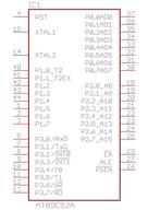
The key thing to note for Arduino users is that usually, symbols are not drawn to scale, and their pins can be shown anywhere on the symbol and in any order. Here's an Atmel microcontroller symbol from the Eagle library:
|  |
| |
However, it is quite possible to make a symbol that is a full-size scale drawing of an Arduino printed circuit board.
A library symbol isn't usable unless it has been incorporated into a 'device' by mounting it in a package. The pins of the symbols must be connected to corresponding pads on the package and all pins must be accounted for. When you design a PCB, the packages you place on it are mapped automatically to the symbols on the schematic drawing. For that reason, you have to define both the package and its connections, though you probably won't be using packages with Arduino.
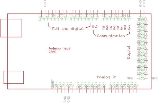
Here's one possible presentation of the library symbol I made for the Arduino Mega 2560:
|  |
| |
Drawing the circuit schematic
The designer places library symbols on the design space, and interconnects their pins (using the NET command, not WIRE...). You can move parts and wires around the drawing and the connections will follow. You can adjust the connecting wires to make them look neat. They can be made thicker than the default setting, but I don't think you can change their colour (green). A nice thing about Eagle is that items are unually placed automatically on the appropriate drawing layer, though you can change the layer for non-electrical items.
The next step, which we don't need, would be to transform the network of virtual wires to the intricate network of tracks on the PCB that interconnect the packages.
Drawing an Arduino circuit schematic
If you look at an Arduino reference design schematic in Eagle, you'll see a collection of interconnected integrated circuits, resistors and so on. You can view the resulting Arduino PCB card as a whole, but that is of no interest unless you want to build your own or design a new model.
What I did for midiTemperament tuning aid was to make a library device in which the complete printed circuit of an Arduino PCB is represented, to scale, as an Eagle symbol, not a PCB. For that to work in the library I also had to make an Eagle package (again a scale image of the PCB) that will probably never be used.
The only slightly unconventional thing (see image above) is that the hollow pads at the end of each pin of the symbol are positioned within the symbol outline, to indicate the rows of connectors as you see them.
|
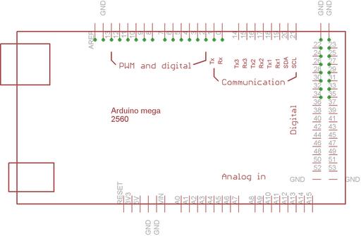
| | | The drawing looks neater if you mask the pads and add junction symbols (small filled green circles). You could perhaps choose to use junction symbols only for the connections you're using: |  |
| |  How to make Eagle accessible to Arduino users |
Drawing Eagle schematics, and modifying other peoples' drawings, isn't difficult if you know where to find the library devices you need. The Eagle library is just a collection of files, to which you can add subdirectories of files using the operating system. Unfortunately, the complete library is a bit intimidating if you don't know much about electronics.
Beginners sometimes find it difficult to find their way around the Eagle library. The easiest way is to do a web search: 'eagle library component name'. This may give links both to the Eagle site and to sites like the present one. Don't assume that users' contributions are error-free.
We could think about what should be put into a smaller specific Eagle-Arduino library subdirectory that might be proposed for general distribution.
The directory would contain the boards themselves, presented as Eagle symbols, together some of the devices most frequently used with the Arduino. In case anyone needs a device that isn't in the library and doesn't know how to make one, it should be possible to provide a few generic ones with just the contact pads that could be annotated ad hoc on the schematic drawing.
I found one or two defective library files on the web, so some kind of expert evaluation of contributions would be useful. To begin with, we could decide on a suitable symbolic presentation for the Arduino boards.
|
| |  Download Eagle libraries | You can download below the Eagle library file I made for for the Arduino Mega. Please let me know if there are any errors.
I've also modified one of the Hitachi-type text LCD displays that were supplied in the Eagle library, to add the backlight connections and render it generic size-wise. Like my Mega symbol, the LCD symbol was provided with the pins on the same scale as the real device. If you don't use the backlight, just don't draw the connections to pins 15 and 16.
A lot of people have been looking for an Eagle library of the ULN2803A Darlington transistor array, which is usually the best choice for connecting digital outputs to LEDs, motors, relays and so on (you don't need any additional components on the input side). The only one I could find on the web had a mistake that made the library unusable. I've corrected that, though I'm not sure I've got my head round automatic part numbering; if you need that you'll know how to fix it.
| | Download Eagle library for Arduino Mega 2560 |
|
|
| Copyright © 2013. Tous droits réservés. | 13 April 2013 | Contact: crl@chrblee.net |
|
|
|

